Month Selector - Click to see posts from a particular month only

Thursday, April 23, 2020

From copper to PCB [Part 3] - more than Logical View : Footprints

                                     
So, after we have the logical diagram and most accurately correct diagram, we have to attach footprints to them, that is what component will look like what when placed on a physical design. As this is something we will touch and feel in real life, so the PCB design process has two divisions, one the logical circuit design and other the physical design, both are equally important and the physical design depends on the logical design.


These footprints I am talking of are provided by manufacturers itself and some by PCB manufacturers also, and after we make logical diagrams we have to attach them or in some softwares they are 
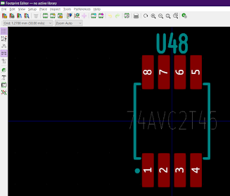
automatically attached for general non-conflicting components.  The footprints are the white coloured markings we see for most PCBs, which is just below the components are placed.


In some cases we might have to attach special parts like a heat sink or a some display whose exterior part is not given in footprint in that case we can manually add a symbol also or do it during physical design process.

0 comments:

Post a Comment

About our Original Photographs

All the Photograph Posts are original and belongs to this blog, Do not use them without credits or mentioning that they are from this blog or who shot the original picture.